3.7.2 - Prospective
short-circuit current (PSC)
The current which is likely to flow in
a circuit if line and neutral cables are short circuited
is called the prospective short circuit current (PSC). It
is the largest current which can flow in the system. and
protective devices must be capable of breaking it safely.
The breaking capacity of a fuse or of a circuit breaker
is one of the factors which need to be considered in its
selection. Consumer units to BS EN 60439-4 and BS 88 (HBC)
fuses are capable of breaking any probable prospective short-circuit
current, but before using other equipment the installer
must make sure that their breaking capacity exceeds the
PSC at the point at which they are to he installed.
The effective breaking capacity of overcurrent
devices varies widely with their construction. Semi-enclosed
fuses are capable of breaking currents of 1 kA to 4 kA depending
on their type. whilst cartridge fuses to BS 1361 will safely
break at 16.5 kA for type 1 or 33 kA for type II. BS 88
fuses are capable of breaking any possible short-circuit
current. Miniature circuit breakers to BS EN60898 have their
rated breaking capacity marked on their cases in amperes
(not kA) although above 10000 A the MCB may be damaged and
lower breaking currents (75% for 10000 A and 50% above that
level) must be used for design purposes.
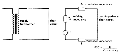
Prospective short circuit
current is driven by the e.m.f. of he secondary winding
of the supply transformer through an impedance made up of
the secondary winding and the cables from the transformer
to the fault {Fig 3.21}. The impedance of the cables will
depend on their size and length, so the PSC value will vary
throughout the installation, becoming smaller as the distance
from the intake position increases. (313-01-01] requires
the PSC to be 'assessed' by 'calculation, measurement, enquiry
or inspection'. In practice, this can be difficult because
it depends to some extent on impedance's which are not only
outside the installation in the supply system, but are also
live. If the impedance of the supply system can be found,
a straightforward calculation using the formula of {Fig
3.21} can be used, but this is seldom the case. An alternative
is to ask the local Electricity Company. The problem here
is that they are likely to protect themselves by giving
a figure which is usually at least 16 kA in excess of the
true value. The problem with using this figure is that the
higher the breaking capacity of fuses and circuit breakers
are (and this must never be less than the PSC for the point
at which they are installed), the higher will be their cost..
{Table 3.6} gives a method of arriving at PSC if the type
and length of the service cable is known,
 |
Fig 3.21 Prospective short circuit current (PSC)
|
Table 3.6 - Estimation of PSC
at the intake position
|
|
Length of supply cable (m)
|
PSC (kA) up to 25mm2 AI,
|
PSC (kA) over 35mm2 AI,
|
|
-
|
16mm2 Cu
supply cable
|
25mm2 Cu supply cable
|
|
5
|
10.0
|
12.0
|
|
10
|
7.8
|
9.3
|
|
15
|
6.0
|
7.4
|
|
20
|
4.9
|
6.2
|
|
25
|
4.1
|
5.3
|
|
30
|
3.5
|
4.6
|
|
40
|
2.7
|
3.6
|
|
50
|
2
|
3.0
|
The table is not applicable
in London, where the density of the distribution system
means that higher values may apply. In this case it will
be necessary to consult London Electricity.
There are two methods for measuring the
value of PSC, but these can only be used when the supply
has already been connected. By then, the fuses and circuit
breakers will already be installed.
The first method is to measure the impedance
of the supply by determining its voltage regulation, that
is, the amount by which the voltage falls with an increase
in current. For example, consider an installation with a
no-load terminal voltage of 240 V. If, when a current of
40 A flows, the voltage falls to 238 V, the volt drop will
be due to the impedance of the supply.
| Thus Zs |
= systems volt drop =
|
240 – 238 W
|
= 2 W
=
|
0.05 W |
| |
current
|
40
|
40
|
|
| Then PSC |
= Uo =
|
240 A
|
= 4800 A or 4.8 kA |
| |
Zs
|
0.05
|
|
A second measurement method is to use a
loop impedance tester see {
5.3 and 8.6.2
} connected to phase and neutral (instead of phase
and earth) to measure supply impedance. This can then be
used with the supply voltage as above to calculate PSC.
Some manufacturers modify their earth-loop testers so that
this connection is made by selecting 'PSC' with a switch.
The instrument measures supply voltage, and calculates,
then displays, PSC.
A possible difficulty in measuring PSC,
and thus being able to use fuses or circuit breakers with
a lower breaking capacity than that suggested by the Supply
Company, is that the supply may be reinforced. More load
may result in extra or different transformers and cables
being installed, which may reduce supply impedance and increase
PSC.