5.8.4 - Electrical separation
Safety from shock can sometimes be ensured
by separating a system completely from others so that there
is no complete circuit through which shock current could
flow. It follows that the circuit must be small to ensure
that earth impedance's are very high and do not offer a
path for shock current (see
{Fig 5.3(b)}). The source of supply for such a circuit
could be a battery or a generating set, but is far more
likely to be an isolating transformer with a secondary winding
providing no more than 500 V. Such a transformer must comply
with BS EN 60742, having a screen between its windings and
a secondary winding which has no connection to earth.
There must be no connection to earth and
precautions must he taken to ensure, as far as possible,
that earth faults will not occur. Such precautions would
include the use of flexible cords without metallic sheaths,
using double insulation, making sure that flexible cords
are visible throughout their length of run, and so on. Perhaps
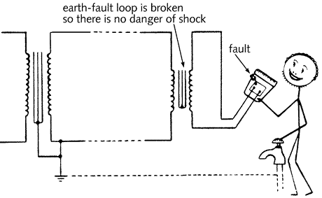
the most common example of a separated circuit is the bathroom
transformer unit feeding an electric shaver. By breaking
the link to the earthed supply system using the double wound
transformer, there is no path to earth for shock current
(see {Fig 5.21}).
Fig 5.21 Bathroom shaver
socket to BS EN 60742
|