IntroductionThe
purpose of this document is to give guidance to approved contractors and suppliers
who are engaged in the fire stopping of service penetrations in fire rated
structures
using the Astro DL COVER. All service holes through floors and compartment walls
must be fire stopped to prevent the passage of fire, smoke and hot gases.
- Prevent the spread of fire, smoke and hot gases through a building
by containing it in the compartment of origin.
- Maintain the integrity of escape routes from a building.
- Reduce loss or damage to property from the effect of fire and smoke.
- Maintain pressure differential between compartments and ventilation
channels.
Downlighers in ceilings are widely used in commercial buildings.
Each ceiling is subject to fire regulations and where applicable the ceiling construction
needs to be fire rated. However, once a hole has been made in the ceiling for
a downlighter, the integrity of the construction and its ability to perform in
a fire can be reduced significantly. To combat this the ASTRO
DL Cover has been developed to cover maximum protection for holes created by the
introduction of a downlighter and to allow for maximum ease of fitting. In
a fire situation the cover expands internally to fill all the available space
with a highly insulating fire resistant char. Thus, the fire is unable to penetrate
the hole and the cover is able to give additional insulation protection to the
ceiling void to reduce the chance of heat build up and ignition of flammable materials
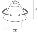
such as accumulated dust and insulation FH DC150 -
150 x 150 - To suit cutout 50 �75 mm FH DC200 - 200 x 200 - To suit
cutout 75-100 mm FH DC250 - 250 x 250 - To suit cutout 100-140mm FH
DC300 - 300 x 170 - To suit cutout 145 -270mm FH DC350 - 350
X 230 - To suit cutout 145-270 mm
| |  |
Step One: Grasp legs firmly and roll cover into
a tight cylinder. Ensure wiring loom is through slot before installation.
|  |
Step Two: Keeping a tight grip on the legs, feed the cover through
the cut out made for the downlighter. |
 |
Step Three: Ensure cover has sprung back into its original cone shape. (a) Grasp legs and pull down until L section clears the
underside of the ceiling. (b) Move legs out until vertical part of L section normal.is
flush with the side of the cut out. | 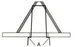 |
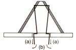
Step Four: Release legs so that they grip the underside of the tile.Remove
the excess of both legs. Cut at point A.Once cover is in place, downlighter can
be fitted as normal. |
The completed installation. 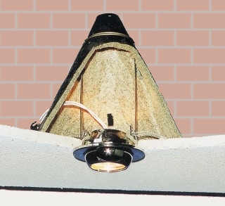
| 
| 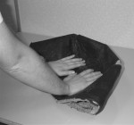 | Step One: | Flatten
the cover | | 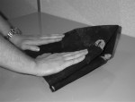
| Step
Two: | Fold the cover
into quarters by folding it in half once .... | 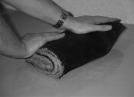 | .....
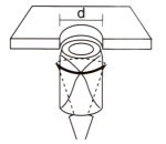
and then folding it in half again. | 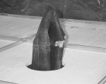 | Step Three: | Pass
the folded cover through the aperture. | 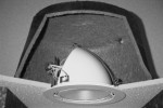 | Step
Four: | Then
fit the downlighter cover as per the manufactures's instructions - cables may
be pushed through the vent slots in the cover. Check and ensure
that there is a distance of 20mm minimum between the downlighter cover and any
insulation or acoustic filling in the void. | | Remote
gearboxes and transformers must be situated outside of the downlighter cover. |
| The completed
installation. 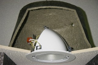
| Compliance Intumescent
downlighter covers are manufactured in the EU, meeting the highest quality standard
in compliance with ISO EN 9001:2000 . Testing certification
Passed
and certified at BRE to BS EN 1365-2 :200
Test report no. CC 203791A.
Passed
and certified at Chiltern International Fire to BS 476 Part 22 1987.
Test
report no. CHILT/A02166B
Passed and certified at Chiltern International Fire
to BS 476 Part 23 1987.
Test report no. FEA/F00063
Storage
and disposal
Astro DL Covers should be stored indoors. No shelf life is given
as this product will not deteriorate in storeage. |
| |
| As part of our policy of ongoing
improvements, we reserve the right to modify, alter or change product specifications
without giving notice. Product illustrations are representations only. All information
contained in this document is provided for guidance only, and as TLC has no control
over the installation methods of the products, or of the prevailing site conditions,
no warranties expressed or implied are intended to be given as to the actual performance
of the products mentioned or referred to, and no liability whatsoever will be
accepted for any loss, damage or injury arising from the use of the information
given of products mentioned or referred to herein. TOP
OF  PAGE PAGE | |