3.6.4 - Circuit breakers
Circuit breakers operate using one or both
of two principles. They are:
1. - Thermal operation relies on
the extra heat produced by the high current warming a bimetal
strip, which bends to trip the operating contacts,
2. - Magnetic operation is due to
the magnetic field set up by a coil carrying the current,
which attracts an iron part to trip the breaker when the
current becomes large enough.
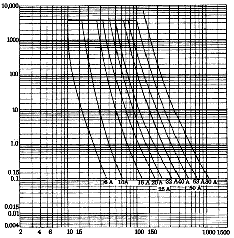
Fig 3.15 Time/current
characteristics of cartridge fuses to BS 88 Part 2
Thermal operation is slow, so it is not
suitable for the speedy disconnection required to clear
fault currents. However, it is ideal for operation in the
event of small but prolonged overload currents. Magnetic
operation can be very fast and so it is used for breaking
fault currents; in many cases, both thermal and magnetic
operation are combined to make the circuit breaker more
suitable for both overload and fault protection. It must
be remembered that the mechanical operation of opening the
contacts takes a definite minimum time, typically 20 ms,
so there can never be the possibility of truly instantaneous
operation. A typical time/current characteristic for a circuit
breaker is shown {Fig.
3.12(b)}
All circuit breakers must have an indication
of their current rating. Miniature circuit breakers have
fixed ratings but moulded case types can be adjusted. Such
adjustment must require the use of a key or a tool so that
the rating is unlikely to be altered except by a skilled
or instructed person.
There are many types and ratings of moulded
case circuit breakers, and if they are used, reference should
be made to supplier's literature for their characteristics.
Miniature circuit breakers are manufactured in fixed ratings
from 5 A to 100 A for some types, and in six types, type
B giving the closest protection. Operating characteristics
for some of the more commonly used ratings of types 1, 3,
B and D are shown in {Figs
3.16 to 3.19}. The characteristics of Type C circuit
breakers are very similar to those of Type 3.
BS3871, which specified the miniature circuit
breakers Types 1 to 4 was withdrawn in 1994 and has been
replaced with BS EN 60898:1991 (EN stands for "European
norm"), although it is possible that circuit breakers
to the old standard will still be on sale for five years
from its withdrawal. In due course, it is intended that
only types B, C and D will be available, although it will
be many years before the older types cease to be used. Short
circuit ratings for the newer types will be a minimum of
3 kA and may be as high as 25 kA - the older types had short
circuit ratings which were rarely higher than 9 kA.
The time/current characteristics of all
circuit breakers {Figs
3.16 to 3.19} have a vertical section where there is
a wide range of operating times for a certain current. Hence,
with a fixed supply voltage, the maximum earth fault loop
impedance is also fixed over this range of time. The operating
current during the time concerned is a fixed multiple of
the rated current. For example, a Type 2 MCB has a multiple
of 7 (from {Table 3.3}) so a 30 A device of this type will
operate over the time range of 0.04 s to 8 s at a current
of 7 x 30 A = 210 A.
Table 3.3 Operating time
ranges and current multiples for MCBs
over fixed current section of characteristic
|
MCB Type
|
Range of operating times (s)
|
Current multiple of rating
|
|
1
|
0.04 to 20
|
x4
|
|
2
|
0.04 to 8
|
x7
|
|
3
|
0.04 to 5
|
x10
|
|
B
|
0.04 to 13
|
x5
|
|
C
|
0.04 to 5
|
x10
|
|
D
|
0.05 to 3
|
x20
|
Table
3.4 A comparison of types of protective device
|
Semi-enclosed fuses
|
HBC fuses
|
Miniature circuit breakers
|
|
Very low initial cost
|
Medium initial cost
|
High initial cost
|
|
Low replacement cost
|
Medium replacement cost
|
Zero replacement cost
|
|
Low breaking capacity
|
Very high breaking capacity
|
Medium breaking capacity
|
Table
3.5 Comparison of miniature circuit breaker types
|
Type
|
Will not trip in
|
Will trip in
|
Typical application
|
|
|
100ms at rating
|
100ms at rating
|
|
|
1
|
2.7 x
|
4 x
|
Low inrush currents (domestic installations) |
|
2
|
4 x
|
7 x
|
General purpose use |
|
3
|
7 x
|
10 x
|
High inrush currents (motor circuits) |
|
B
|
3 x
|
5 x
|
General purpose use (close protection) |
|
C
|
5 x
|
10 x
|
Commercial and industrial applications
with fluorescent fittings |
|
D
|
10 x
|
50 x
|
Applications where high in-rush currents
are likely (transformers, welding machines) |
{Table 3.4} shows a comparison
of the three main types of protective device in terms of
cost, whilst {Table 3.5} compares the available types of
MCB.