3.6.5 - Protecting
conductors
The prime function of overload protection
is to safeguard conductors and cables from becoming too
hot. Thus the fuse or circuit breaker rating must be no
greater than that of the smallest cable protected. Reference
to the time/current characteristics of protective devices
{Figs
3.13 to 3.19} shows that a significantly greater current
than the rated value is needed to ensure operation.
Thus, the current at which the protective
device operates must never be greater than 1.45 times the
rating of the smallest cable protected. For example, consider
a cable system rated at 30 A and protected by a miniature
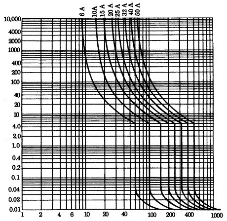
circuit breaker type 3, rated at 32 A. Reference to (Fig
3.17 shows that a prolonged overload of about 38 A will
open the breaker after about 104 seconds (about two and
a half hours!). The ratio of operating current over rated
current is thus 38/30 or 1.27, significantly lower than
the maximum of 1.45. All circuit breakers and HBC fuses
listed in {3.6.2
sections 2 and 3} will comply with the Regulations
as long as their rating does not exceed that of the smallest
cable protected.
Semi-enclosed (rewirable) fuses do not
operate so closely to their ratings as do circuit breakers
and HBC fuses. For example, the time/current characteristics
of
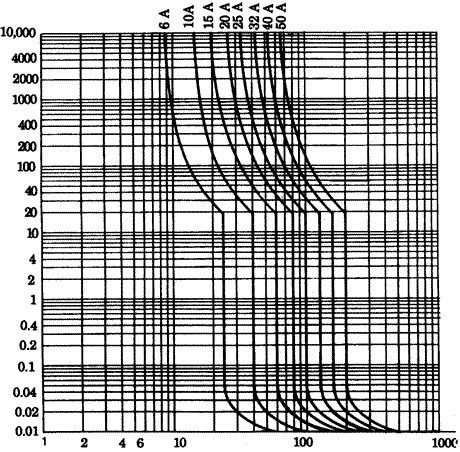
Fig 3.16 Time/current
characteristics for some miniature circuit breakers Type
1
Fig 3.17 Time/current
characteristics for some miniature circuit breakers Type
3.
Type C -MCBs have very similar characteristics to Type 3
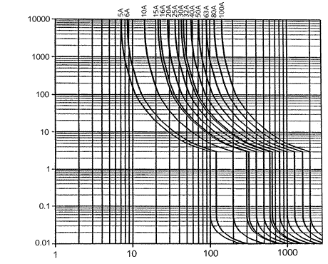
{Fig
3.13} show that about 53 A is needed to ensure the operation
of a 30 A fuse after 10,000 s, giving a ratio of 53/30 or
1.77. For rewirable fuses, the Regulations require that
the fuse current rating must not exceed 0.725 times the
rating of the smallest cable protected. Considering the
30 A cable protected by the 32 A miniature circuit breaker
above, if a rewirable fuse replaced the circuit breaker,
its rating must not be greater than 0.725 x 30 or 21.8 A.
Since overload protection is related to
the current-carrying capacity of the cables protected, it
follows that any reduction in this capacity requires overload
protection at the point of reduction. Reduced current-carrying
capacity may be due to any one or more of:
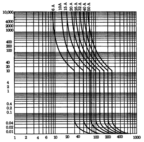
Fig 3.18 Time/current
characteristics for some miniature circuit breakers Type
B
Fig 3.19 Time/current
characteristics for some miniature circuit breakers Type
D
1.
- a reduction in the cross-sectional area of the
cable
2. - a different type of cable
3. - the
cable differently installed so that its ability to lose
heat is reduced
4. - a
change in the ambient temperature to which the cable is
subjected
5. - the
cable is grouped with others.
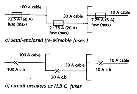
{Figure 3.20} shows part of a system to
indicate how protection could be applied to conductors with
reduced current carrying capacity.
Fig 3.20 Position and
rating of devices for overload protection
In fact, the calculated fuse sizes for
{Fig 3.20a)} of 72.5 A, 21.75 A and 7.25 A are not available,
so the next lowest sizes of 60 A, 20 A and 5 A respectively
must be used. It would be unwise to replace circuit breakers
with semi-enclosed fuses because difficulties are likely
to arise. For example, the 5 A fuse used as the nearest
practical size below 7.25 A is shown in {Fig
3.13} to operate in 100 5 when carrying a current of
10 A. Thus, if the final circuit is actually carrying 10
A, replacing a 10 A circuit breaker with a 5 A fuse will
result in the opening of the circuit. The temptation may
be to use the next semi-enclosed fuse size of 15 A, but
that fuse takes nearly seven minutes to operate at a current
of 30 A. Clearly, the cable could well be damaged by excessive
temperature if overloaded.
The device protecting against overload
may be positioned on the load side of (downstream from)
the point of reduction, provided that the unprotected cable
length does not exceed 3 m, that fault current is unlikely,
and that the cable is not in a position that is hazardous
from the point of view of ignition of its surroundings.
This Regulation is useful when designing switchboards, where
a short length of cable protected by conduit or trunking
feeds a low-current switch fuse from a high current fuse
as in {Fig
6.2}.
All phase conductors must be protected,
but attention must be paid to the need to break at the same
time all three line conductors to a three-phase motor in
the event of a fault on one phase, to prevent the motor
from being damaged by 'single-phasing'. Normally the neutral
of a three phase system should not be broken, because this
could lead to high voltages if the load is unbalanced. Where
the neutral is of reduced size, overload protection of the
neutral conductor may be necessary, but then a circuit breaker
must be used so that the phases are also broken.