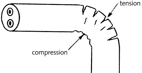
4.4.2 - Cable bends
If an insulated cable is bent too sharply,
the insulation and sheath on the inside of the bend will
be compressed, whilst that on the outside will be stretched,
This can result in damage to the cable as shown in {Fig
4.16}.
The bending factor must be used to assess the minimum acceptable
bending radius, values for common cables being given in
{Table 4.11}.
Fig 4.16 Damage to cable
insulation due to bending
|
Type of insulation
|
Overall diameter
|
Bending factor
|
|
p.v.c.
|
Up to 10mm
|
3 (2)
|
|
p.v.c.
|
10mm to 25mm
|
4 (3)
|
|
p.v.c.
|
Over 25mm
|
6
|
|
mineral
|
any
|
6 *
|
| The figures in
brackets apply to unsheathed single-core stranded p.v.c.
cables when installed in conduit, trunking or ducting. |
| * Mineral insulated
cables may be bent at a minimum radius of three cable
diameter provided that they will only be bent once. This is because the copper sheath will ‘work
harden’ when bent and is likely to crack if straightened
and bent again. |
Table 4.11 Bending factors
for common cables
The figures in brackets apply to unsheathed
single-core stranded p.v.c. cables when installed in conduit,
trunking or ducting.
* Mineral insulated cables may be bent
at a minimum radius of three cable diameter provided that
they will only be bent once. This is because the copper sheath will ‘work
harden’ when bent and is likely to crack if straightened
and bent again.
The factor shown in the table is that by
which the overall cable diameter {Fig
4.12}
must be multiplied to give the minimum inside radius
of the bend. For example,
2.5 mm² twin with protective conductor sheathed cable
has a cross-section 9.7 mm
x 5.4 mm. Since
the Table shows a factor of 3 for this size, the minimum
inside
radius of any bend must be 3 x 9.7 = 29.1 mm.
|