8.4.2 - Ring final circuit continuity
The ring final circuit, feeding 13 A sockets,
is extremely widely used, both in domestic and in commercial
or industrial situations. It is very important that each
of the three rings associated with each circuit (phase,
neutral and protective conductors) should be continuous
and not broken. If this happens, current will not be properly
shared by the circuit conductors. {Fig 8.4} shows how this
will happen. {Fig 8.4(a)} shows a ring circuit feeding ten
socket outlets, each of which is assumed to supply a load
taking a current of 3 A. In simple terms, current is then
shared between the conductors, so that each could have a
minimum current carrying capacity of 15 A. {Fig 8.4(b)}
shows the same ring circuit with the same loads, but broken
between the ninth and tenth sockets. It can be seen that
now one cable will carry only 3 A whilst the other (perhaps
with a current rating of 20 A) will carry 27 A. The effect
will occur in any broken ring, whether simply one live conductor
or both are broken.
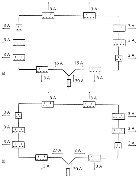 |
Fig 8.4 - illustrating
the danger of a break in a ring final circuit
a) unbroken ring with correct current sharing
b) broken ring with incorrect current sharing
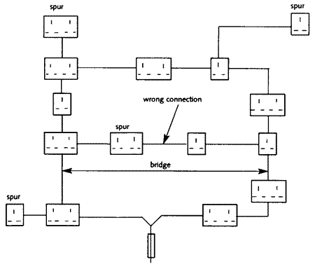
It is similarly important that there should
be no 'bridge' connection across the circuit. This would
happen if, for example, two spurs from different points
of the ring were connected together as shown
in {Fig 8.5}, and again could result in incorrect load sharing
between the ring conductors.
The tests of the ring final circuit will
establish that neither a broken nor a bridged ring has occurred.
The following suggested test is based on the Guidance Note
on Inspection and Testing issued by the IEE.
Fig 8.5 - A 'bridged'
ring final circuit
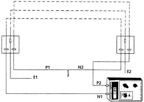
Test 1
This test confirms that complete rings exist and that
there are no breaks. To complete the test, the two ends
of the ring cable are disconnected at the distribution board.
The phase conductor of one side of the ring and the neutral
from the other (P1 and N2J are connected together, and a
low resistance ohmmeter used to measure the resistance between
the remaining phase and the neutral (P2 and Ni). {Figure
8.6} shows that this confirms the continuity of the live
conductors. To check the continuity of the circuit
protective conductor, connect the phase and CPC of different
sides together (P1 and E2) and measure the resistance between
phase and CPC of the other side (P2 and El). The result
of this test will be a measurement of the resistance of
live and protective conductors round the ring, and if divided
by four gives (Ri + R2) which will conform with the values
calculated from {Table
5.5}.
Fig 8.6 - Test to confirm
the continuity of a ring final circuit
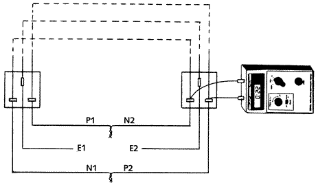
Test 2
This test will confirm the absence of bridges in the
ring circuit, see {Fig 8.7}. First, the phase conductor
of one side of the ring is connected to the neutral of the
other (P1 and N2) and the remaining phase and neutral are
also connected together (P2 -and Ni). The resistance is
then measured between phase and neutral contacts of each
socket on the ring. If the results of these measurements
are all substantially the same (within 0.05 Ohms), the absence
of a bridge is confirmed. If the readings are different,
this will indicate the presence of a bridge or may be due
to incorrect connection of the ends of the ring. If they
are connected P1 to NI and P2 to N2 then readings will increase
or reduce as successive measurements round the ring are
taken, as is the case where a bridge exists. Whilst this
misconnection is easily avoided when using sheathed cables,
a mistake can be made very easily if the system consists
of single-core cables in conduit. It may be of interest
to note that the resistance reading between phase and neutral
outlets at each socket should be one quarter of the phase/neutral
reading of Test 1.
Measurements are also taken at each socket
on the ring between the phase and the protective conductor
with the temporary connection made at the origin of the
ring between P1 to E2 and between P2 to El. Substantially
similar results will indicate the absence of bridges.
Fig 8.7 - Test to confirm
the absence of bridges in a ring final circuit