8.6.2 - Measuring earth-fault loop impedance and
prospective short-circuit current
The nature of the earth-fault loop and
its significance have been considered in detail in {5.3}.
Since the loop includes the resistance of phase and protective
conductors within the installation, the highest values will
occur at points furthest from the incoming supply position
where these conductors are longest. A measurement within
the installation will give the complete earth-fault loop
impedance far the point at which it is taken (Zs), or the
earth-fault loop impedance external to the installation
(Ze) may be measured at the supply position. Internal loop
measurements should be taken at points furthest from the
intake to give the highest possible results.
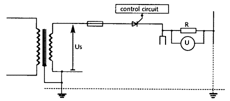
In simple terms, the impedance of the phase-to-earth
loop is measured by connecting a resistor (typically 10
Ohms) from the phase to the protective conductor as shown
in {Fig 8.17}. A fault current, usually something over 20
A, circulates in the fault loop, and the impedance of the
loop is calculated within the instrument by dividing
supply voltage by the value of this current. The resistance
of the added resistor must be subtracted from this calculated
value before the result is displayed. An alternative method
is to measure the supply voltage both before and whilst
the loop current is flowing. The difference is the volt
drop in the loop due to the current, and loop impedance
is calculated from voltage difference divided by current.
Fig 8.17 - Simple principle
of earth-fault loop testing
Since the loop current is very high, its
duration must be short and must be limited to two cycles
(or four half-cycles) or 40 ms for a 50 Hz supply. The current
is usually switched by a thyristor or a triac, the firing
time being controlled by an electronic timing circuit It
is very important to have already checked the continuity
of the protective system before carrying out this test.
A break in the protective system, or a high resistance within
it, could otherwise result in the whole of the protective
system being directly connected to the phase conductor for
the duration of the test. Commercial testers are usually
fitted with indicator lamps to confirm correct connection
or to warn of reversed polarity. {Fig 8.18} shows a typical
earth-fault loop tester connected to a socket outlet so
that its loop impedance can be measured. If the circuit
to be measured includes socket outlets, the tester is connected
as indicated in {Fig 8.18}. Special leads for connection
to phase and to earth are provided by suppliers for all
other circuits.
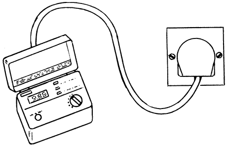 |
Fig 8.18 - Earth-fault
loop tester connected for use
Before testing, the main equipotential
bonding conductors are disconnected (BUT NOT THE CONNECTION
WITH EARTH) to prevent parallel earth return paths and to
ensure that there is no reliance on the service pipes for
gas and water for effective earthing, (REMEMBER TO RECONNECT
THE MAIN EQUIPOTENTIAL BONDING AFTER THE TEST).
Tests must be carried out at the origin
of the installation, at each distribution board, at all
fixed equipment, at all socket outlets, at 10% of all lighting
outlets (choosing points farthest from the supply) and at
the furthest point of every radial circuit. The test should
be repeated at least once to allow for the effect of transient
variations in the supply voltage.
A modified version of the earth-fault loop
tester, which effectively measures the phase to neutral
impedance and calculates then displays the value of the
current which would flow if the supply voltage were applied
to this impedance are readily available. The principle of
such a PSC tester is described in {3.7.2}.
Since the test result is dependent on the
supply voltage, small variations will affect the reading.
Thus, the test should be repeated several times to ensure
consistent results. The test resistor will be connected
across the mains for the duration of each test. and will
become very hot if frequent tests are made. Some testers
will then 'lock out' to prevent further testing until the
resistor temperature falls to a safe value.
The
earth fault loop impedance measured as described will be
for installation cables at ambient temperature, unless the
circuit concerned has been in use immediately before the
test, when it will be the impedance at normal operating
temperature. Under normal operating conditions, cable temperature
will rise, and so will the resistive component of the impedance.
This effect is difficult to calculate, and a practical alternative
is to ensure that the measured values of earth fault loop
impedance do not exceed three quarters of the maximum values
shown in {Tables
5.1, 5.2 or 5.4} as appropriate.
The effect of supply voltage on the calculation
of earth fault loop impedance is considered in {5.3.4}.
A
circuit protected by an RCD will need special attention,
because the earth-fault loop test will draw current from
the phase which returns through the protective system. This
will cause an RCD) to trip. Therefore, any RCDs must be
bypassed by short circuiting connections before earth-fault
loop tests are carried out. It is, of course, of the greatest
importance to ensure that such connections are removed after
testing. One manufacturer supplies a patented loop tester
which does not require RCDs to be short circuited and which
will not cause them to trip
when the earth-fault loop test is made. Some instruments limit the test current to
15 mA so as not to trip RCDs with ratings of 30 mA and above.
Whilst such tests may often be useful, they do not test
the integrity of the system under fault current conditions.
When loop testing at lighting units controlled
by passive infrared detectors (PIRs), there may he damage
to the associated electronic switches unless they are short-circuited
before testing.
An alternative to the use of a dedicated
earth-fault loop impedance tester is to measure the combined
resistance of the phase and protective conductors from the
incoming position to the point for which earth-fault loop
impedance is required (this is R1 + R2 - see
{8.4.4}) and to add to it the external earth-fault loop
impedance (Ze) which can be obtained from the electricity
supplier. All earth-fault loop impedance test results should
be carefully compared with the data in [Tables 41B and 41D],
adjusted to allow for ambient temperature, or with figures provided by the designer. To ensure
that ambient temperature is taken into account, the results
should never exceed three quarters of the values given in
[Tables 41B and 41D].